PRODUCT SUMMARY
Designed for lower horsepower machines, Metal Masters give outstanding performance with their unique non-rotating Frustum inserts.
PRODUCT SPECIFICATIONS
| Effective Cutting Dia. |
No. Inserts |
Shank Dia. |
Maximum O.D. |
| 2.00 | 1 | .75 | 2.70 |
| Effective Cutting Dia. |
No. Inserts |
Shank Dia. |
Maximum O.D. |
| 2.00 | 3 | .75 | 2.70 |
| Part No. | Grade | Coating |
| 25P | C2 | None |
| 25PC | C2 | TiN-TiC-AL2O3 |
| 55P | C5 | None |
| 55PC | C5 | TiN-TiC-TiN |
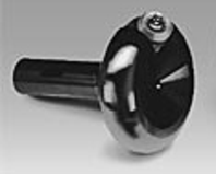
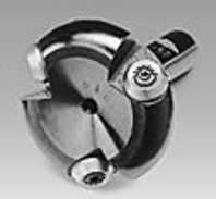
FLYCUTTERS
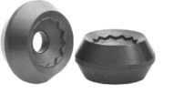
FRISTUM INSERTS
DISCOVER THE COMPETITIVE EDGE: METAL MASTER MILLING CUTTERS w/FRUSTUM INSERTS
 Frus’tum/n:
That part of a cone-shaped solid next to the base and formed by cutting off the top with a plane parallel to the base (Websters Dictionary).
Frustum is tougher, works longer
We’ve turned the corner to twenty-first century technology. When you use Metal Master Milling Cutters with patented Frustum* inserts you don’t have to sacrifice toughness and durability for speed (or vice versa) like you do when you choose between conventional inserts. In fact, Frustum inserts eliminate the need to compare positive versus negative geometries, period. Now, you just compare Frustum to everything else. And Frustum beats everything else. Because mass is relocated outside the cutting edge where it strengthens, stabilizes, and aids in heat dissipation. Even the severe shock associated with interrupted cuts is no problem. In other words, Frustum lasts longer. So, productivity climbs.
| Here’s How They Compare |  |
 |
 |
 |
| Feature | Conventional Positive | Conventional Negative | Round/Positive | Frustum |
| Metal Removal Rate (per H P.) | • High | Low | • High | • High |
| Operating Speed | • High | Low | • High | • High |
| Efficiency of Power Use | • High | Low | • High | • High |
| Heat Dissipation | Poor | • Fair | Poor | Excellent |
| Number of Usable Sides | One | • Two | One | • Two |
| Edge Strength | Weak | • Strong | Weak | • Strongest |
| Insert Life | Short | • Average | Short | • Long |
| Workpiece Distortion | • Less | More | • Less | • Less |
| Rigidity Requirement | • Less | More | • Less | • Less |
| Versatility of Applications | Limited | Limited | Limited | • Many |
Going beyond round
Compared to other shapes, conventional round inserts have two advantages. They are inherently stronger. And, they have more cutting edges. Like other conventional geometries however, conventional round inserts still force you to choose between efficiency (positive) and insert life (negative). Frustum, on the other hand, goes beyond round. When compared to a conventional round insert design, a Frustum insert has a major advantage. A Frush1m insert’s cutting edge has the reinforcement of the additional mass that other round inserts don’t have. When you go beyond round, you don’t have to choose between efficiency and longer insert life. You get both.
Boost your productivity curve upward
When you go beyond conventional thinking you go beyond conventional results. The Frush1m design eliminates angles and straight lines, flats and squares. And it’s more than simply round. It’s a unique and stronger geometry. And it’s this geometry that allows you to lower your costs and increase the productivity of every milling machine in your shop. Not only will you see it happen-your trained ear will hear it happen.
Faster removal rates. More chips, lower costs per hour
Frustum inserts permit significantly higher operating speeds because of the high efficiency of the cutting edge. The amount of horsepower converted into cutting energy is maximized. You can operate much faster than you can with conventional tungsten carbide inserts. Productivity climbs even higher.
There’s two sides to the story. More than double the cutting indexes
Frustum inserts can boost your productivity another way too. The Frustum double-sided design, combined with the high stability and strength of unconventional, more effective Frustum geometry, provides up to twice as many indexes as conventional inserts.
Frustum Posi-Grip Inserts are versatile
Name your material. Chances are Frustum inserts can handle it better and faster. As the chart shows, regardless of the finish desired or the feed rate, you only have to inventory four Part Numbers.
Provides outstanding finish
With a large radius and no sharp corners in contact with the part being worked, Frustum inserts can provide a finish as good as 16µ in. (0.4µm) Ra. You may be able to eliminate the need for grinding. So, you may boost productivity even further.
When you put the cutting edge on the inside…Milling productivity goes through the roof
You’re looking at the next step in high-positive milling performance, the all new RTC Metal Master milling system. It’s so far ahead of conventional milling technology that you simply have to see it in action to believe it.
The cutting edge is on the inside
The secret of Metal Master’s performance is a patented new insert geometry that puts the cutting edge on the inside of the round insert. This revolutionary design puts the mass where it’s needed most, in support of the cutting edge, while keeping it out of the way during the cut.
The result is a positive shear angle of 60-degrees, in an insert that’s inherently stronger than any conventional round insert of comparable size, positive or negative. So, now you don’t have to make the trade-off between weak, free cutting, high shear positive rake inserts, and strong, horsepower gobbling negative rake geometries. Now you can have the best of both, and it only gets better from here.
FLYCUTTERS
Quick indexing – Indexing is done quickly and easily on the machine. Simply loosen the screw, rotate insert, tighten screw. Minimizes non-productive downtime.
Rigid body – Built for maximum rigidity. Minimizes deflection which might result in poor surface finish.
“Deep Pocket” design – Rigid support for entire circumference of the insert.
“Solid Shield” – Surrounds insert and directs cutting forces into solid body. Much safer in operation.
Positive location – Precision-machined insert seats assure accurate location and improved surface finishes.
OPERATING SPECIFICATIONS
Important! Please read before using this cutting tool.
Safety -Any cutting tool may shatter if broken. Always wear adequate eye protection.
Coolant – Flood or heavy mist required when machining non-ferrous materials. Ferrous materials may be machined dry if lower cutting parameters are used.
Depth of Cut – Recommended maximum depth of cut is .125 inch (3.2mm). Deeper cuts may cause the clamp screw to loosen.
| OPERATING SPECIFICATIONS | ||||||
| Feeds & Speeds | ||||||
| INSERT SELECTION AND SFM (v) | DEPTH OF CUT | IPT (sz) | ||||
| ft/min (m/min) | Inch (mm) | inch/tooth | ||||
| (mm/insert) | ||||||
| MATERIAL | 25P | 55P | 25PC | 55PC | MM & MFS CUTERS | |
| CARBON STEELS | ||||||
| LOW CARBON | 600-900(185-275) | 800-1200(245-370) | .020-.050(0.50-1.25) | .005-.008(.10-.20) | ||
| 500-800(150-245) | 700-1100(215-335) | .050-.100(1.25-2.50) | .005-.008(.10-.20) | |||
| 600-1000(185-305) | .100-.250(2.50-6.50) | |||||
| MEDIUM CARBON | 500-700(150-215) | 700-900(215-275) | .020-.050(0.50-1.25) | .005-.008(.10-.20) | ||
| 400-600(125-185) | 600-800(185-245) | .050-.100(1.25-2.50) | .005-.008(.10-.20) | |||
| 500-700(150-215) | .100-.250(2.50-6.50) | |||||
| HIGH CARBON | 400-600(125-185) | 600-800(185-245) | .020-.050(0.50-1.25) | .005-.008(.10-.20) | ||
| 300-500(90-150) | 500-700(150-215) | .050-.100(1.25-2.50) | .005-.008(.10-.20) | |||
| 400-600(125-185) | .100-.250(2.50-6.50) | |||||
| ALLOY STEELS | ||||||
| LOW & MEDIUM | 500-600(150-185) | 800-900(245-275) | .020-.050(0.50-1.25) | .005-.008(.10-.20) | ||
| CARBON | 400-500(125-150) | 700-800(215-245) | .050-.100(1.25-2.50) | .005-.008(.10-.20) | ||
| 600-700(185-215) | .100-.250(2.50-6.50) | |||||
| HIGH CARBON | 400-600(125-185) | 700-800(215-245) | .020-.050(0.50-1.25) | .005-.008(.10-.20) | ||
| 300-500(90-150) | 600-700(185-215) | .050-.100(1.25-2.50) | .005-.008(.10-.20) | |||
| 500-600(150-185) | .100-.250(2.50-6.50) | |||||
| TOOL STEELS | ||||||
| HIGH SPEED | 300-400(90-125) | 400-600(125-185) | .020-.050(0.50-1.25) | .005-.007(.10-.18) | ||
| 200-300(60-90) | 300-500(90-150) | .050-.100(1.25-2.50) | .005-.007(.10-.18) | |||
| 200-400(60-125) | .100-.250(2.50-6.50) | |||||
| HOT & COLD WORK | 300-500(90-150) | 500-700(150-215) | .020-.050(0.50-1.25) | .005-.007(.10-.18) | ||
| 200-400(60-125) | 400-600(125-185) | .050-.100(1.25-2.50) | .005-.007(.10-.18) | |||
| 300-500(90-150) | .100-.250(2.50-6.50) | |||||
| MOLD | 400-700(125-215) | 700-1000(215-305) | .020-.050(0.50-1.25) | .005-.007(.10-.18) | ||
| 300-600(90-185) | 600-900(185-275) | .050-.100(1.25-2.50) | .005-.007(.10-.18) | |||
| 500-800(150-245) | .100-.250(2.50-6.50) | |||||
| ARMOR PLATE | 200-300(60-90) | 400-600(125-185) | .020-.040(0.50-1.00) | .005-.007(.10-.18) | ||
| 100-200(30-60) | 300-500(90-150) | .040-.075(1.00-2.00) | .005-.007(.10-.18) | |||
| 200-400(60-125) | .075-.200(2.00-5.00) | |||||
| STRUCTURAL STEELS | 300-400(90-125) | 500-700(150-215) | .020-.060(0.50-1.50) | .005-.008(.10-.20) | ||
| 200-300(60-90) | 400-600(125-185) | .060-.100(1.50-2.50) | .005-.008(.10-.20) | |||
| 300-500(90-150) | .100-.250(2.50-6.50) | |||||
| STAINLESS STEELS | ||||||
| 300 SERIES | 300-400(90-125) | 500-700(150-215) | .020-.060(0.50-1.50) | .005-.008(.10-.20) | ||
| 200-300(60-90) | 400-600(125-185) | .060-.100(1.50-2.50) | .005-.008(.10-.20) | |||
| 300-500(90-150) | .100-.250(2.50-6.50) | |||||
| 400 SERIES | 400-600(125-185) | 700-900(215-275) | .020-.060(0.50-1.50) | .005-.008(.10-.20) | ||
| 300-500(90-150) | 600-800(185-245) | .060-.100(1.50-2.50) | .005-.008(.10-.20) | |||
| 500-700(150-215) | .100-.250(2.50-6.50) | |||||
| PRECIPITATION | 200-400(60-125) | 500-600(150-185) | .020-.060(0.50-1.50) | .005-.008(.10-.20) | ||
| HARDENING | 100-300(30-90) | 400-500(125-150) | .060-.100(1.50-2.50) | .005-.008(.10-.20) | ||
| 300-400(90-125) | .100-.250(2.50-6.50) | |||||
| OPERATING SPECIFICATIONS | ||||||
| Feeds & Speeds | ||||||
| INSERT SELECTION AND SFM (v) | DEPTH OF CUT | IPT (sz) | ||||
| ft/min (m/min) | Inch (mm) | inch/tooth | ||||
| (mm/insert) | ||||||
| MATERIAL | 25P | 55P | 25PC | 55PC | MM & MFS CUTERS | |
| GRAY CAST IRONS | 300-600(90-185) | 700-1000(215-305) | .020-.060(0.50-1.50) | .005-.008(.10-.20) | ||
| 200-500(60-150) | 600-900(185-275) | .060-.100(1.50-2.50) | .005-.008(.10-.20) | |||
| 500-800(150-245) | .100-.250(2.50-6.50) | |||||
| DUCTIBLE CAST IRON | ||||||
| FERRITIC, FERRITIC PEARLITIC & PERLITIC MARTENSITIC | 400-600(125-185) | 700-1000(215-305) | .020-.060(0.50-1.50) | .005-.008(.10-.20) | ||
| 300-500(90-150) | 600-900(185-275) | .060-.100(1.50-2.50) | .005-.008(.10-.20) | |||
| 500-800(150-245) | .100-.250(2.50-6.50) | |||||
| MARTENSITIC & AUSTENITIC | 200-300(60-90) | 300-400(90-125) | .005-.008(.10-.20) | |||
| 100-200(30-60) | 200-300(60-90) | .060-.100(1.50-2.50) | .005-.008(.10-.20) | |||
| 100-300(30-90) | .100-.250(2.50-6.50) | |||||
| MALLEABLE CAST IRONS | ||||||
| FERRITIC | 600-800(185-245) | 1000-1200(215-370) | .020-.060(0.50-1.50) | .005-.008(.10-.20) | ||
| 500-700(150-215) | 900-1100(275-335) | .060-.100(1.50-2.50) | .005-.008(.10-.20) | |||
| 800-1000(245-305) | .100-.250(2.50-6.50) | |||||
| PEARLITIC | 400-600(125-185) | 600-800(185-245) | .020-.060(0.50-1.50) | .005-.008(.10-.20) | ||
| 300-500(90-150) | 500-700(150-215) | .060-.100(1.50-2.50) | .005-.008(.10-.20) | |||
| 400-600(125-185) | .100-.250(2.50-6.50) | |||||
| TEMPERED MARTENSITIC | 200-300(60-90) | 400-500(125-150) | .020-.060(0.50-1.50) | .005-.008(.10-.20) | ||
| 100-200(30-60) | 300-400(90-125) | .060-.100(1.50-2.50) | .005-.008(.10-.20) | |||
| 200-300(60-90) | .100-.250(2.50-6.50) | |||||
| ALUMINUM ALLOYS | ||||||
| WROUGHT | 2000-5000(610-1530) | .020-.100(0.50-2.50) | .005-.010(.10-.25) | |||
| 2000-5000(610-1530) | .100-.300(2.50-7.50) | |||||
| CAST | 1500-3000(460-915) | .020-.100(0.50-2.50) | .005-.010(.10-.25) | |||
| 1500-3000(460-915) | .100-.300(2.50-7.50) | |||||
| MAGNESIUM ALLOYS | 2000-3000(610-915) | .020-.100(0.50-2.50) | .005-.010(.10-.25) | |||
| 2000-3000(610-915) | .100-.300(2.50-7.50) | |||||
| TITANIUM ALLOYS | 80-150(25-45) | .020-.060(0.50-1.50) | .005-.008(.10-.20) | |||
| 80-150(25-45) | .060-.125(1.50-3.25) | |||||
| COPPER ALLOYS | ||||||
| WROUGHT | 800-1400(245-430) | .020-.050(0.50-1.25) | .005-.008(.10-.20) | |||
| 700-1300(215-400) | .050-.100(1.25-2.50) | .005-.008(.10-.20) | ||||
| 600-1200(185-370) | .100-.250(2.50-6.50) | |||||
| CAST | 900-1300(275-400) | .020-.050(0.50-1.25) | .005-.008(.10-.20) | |||
| 800-1200(245-370) | .050-.100(1.25-2.50) | .005-.008(.10-.20) | ||||
| 700-1100(215-335) | .100-.250(2.50-6.50) | |||||
| NICKEL ALLOYS | 100-200(30-60) | .020-.050(0.50-1.25) | .005-.008(.10-.20) | |||
| 100-200(30-60) | .050-.150(1.25-3.75) | |||||
| HIGH TEMPERATURE ALLOYS | 30-100(10-30) | .020-.050(0.50-1.25) | .005-.008(.10-.20) | |||
| 30-100(10-30) | .050-.150(1.25-3.75) | |||||
GENERAL MACHINING PARAMETERS
- Climb milling is strongly recommended over conventional milling in order to prevent the inserts from rubbing when entering the part. With Metal Master Milling Cutters, rubbing will quickly lead to increase friction and heat buildup, drastically reducing insert and cartridge life. (See Illustration)
- Skim Cutting. Due to the unique cutting action of Metal Master Milling Cutters, the part should be lowered .005″ (0.10 mm) to .10″ (0.25 mm) on “return” passes to prevent skim cut. If the cutter is allowed to skim cut, insert life will be drastically shortened.
- Width of Cut. Optimum width of cut is generally two-thirds of the diameter of the cutter.